Che cosa sta cercando?
Effective protection usually requires more than placing a high-temperature sleeve over the wires. Engineers need to evaluate the heat source, available clearance, harness routing, connector position, vehicle movement, installation method and maximum permitted harness temperature.
The most reliable approach is to combine suitable routing with a correctly selected aluminized heat protective sleeve, secure mechanical retention and application-specific thermal validation.
Exhaust manifolds collect hot gases from multiple engine cylinders and direct them toward the rest of the exhaust system. Turbocharger turbine housings and nearby downpipes operate within the same high-temperature flow path.
These components create localized thermal zones within the engine compartment. A wire harness may be separated from the hot surface by an air gap but still receive substantial radiant energy.
Typical wiring located in or near these zones includes:
Because these components may have different temperature limits, the complete harness assembly should be evaluated rather than considering only the conductor or cable jacket.
A common specification mistake is to select a sleeve only from its advertised maximum temperature.
The temperature capability of the sleeve material does not directly establish the temperature that the protected wire harness will reach. Harness temperature is influenced by several variables:
The engineering target should therefore be expressed as a thermal condition, such as the maximum allowed temperature of the cable, connector or harness assembly, rather than only a required sleeve temperature rating.
Before selecting a protective sleeve, determine the dominant method of heat transfer. Exhaust-adjacent wiring may be affected by radiant heat, high ambient temperature, conductive heat or a combination of these conditions.
Radiant heat travels from a hot exhaust or turbocharger surface toward the wire harness without direct physical contact.
This is the condition in which a reflective aluminized sleeve is particularly useful. The reflective surface faces the external heat source and helps reduce the radiant energy absorbed by the underlying textile and wiring.
The complete engine compartment may remain hot after extended operation. In this condition, the harness is exposed not only to one hot surface but also to elevated surrounding air and nearby heated components.
A thin reflective layer may need to be combined with additional insulation when prolonged ambient temperature is a major part of the requirement.
If the harness sleeve touches an exhaust manifold, turbocharger housing or downpipe, heat can transfer through direct conduction.
A reflective surface alone should not be treated as the primary solution for continuous direct contact. The preferred corrective action is normally to improve routing, restore clearance or introduce a suitable source-side shield. Additional insulation may also be required.
Some wiring routes are exposed to hot air leaving the exhaust or turbocharger area. Air movement can carry heat toward connectors or harness branches that are not directly facing the hottest surface.
This should be considered when deciding the length of the protected section. Covering only the point directly opposite the heat source may not protect the complete affected zone.
A thermal sleeve should support good harness routing, not compensate for an avoidable installation problem.
Before adding insulation, review whether the harness can be moved farther from the heat source. Even a modest routing change may reduce radiant exposure and make a thinner, more flexible protection system possible.
Check the complete harness path for:
The minimum clearance should be checked under actual operating movement, not only when the vehicle is stationary and the engine is cold.
There are three basic thermal-management approaches.
A reflective or insulated sleeve is installed around the wiring. This is useful when the harness follows a defined route and there is enough space for the added sleeve thickness.
A separate shield is installed around or between the exhaust component and the wire harness. Examples include formed metal shields, flexible textile barriers and turbocharger insulation systems.
Source-side shielding can reduce the thermal load affecting multiple nearby components rather than protecting one harness section alone.
Restricted engine compartments may require both a source-side shield and a sleeve around the wire harness. This approach may be appropriate where the heat source is intense, clearance is limited or several materials within the harness have low allowable temperatures.
The final design should be validated as a complete assembly rather than assuming that two individually heat-resistant products will automatically meet the required harness temperature.
An exhaust manifold normally presents a strong radiant heat source over a relatively broad surface. Wiring may pass above, beside or behind the manifold because of sensor position, engine architecture or connector routing.
An aluminized fiberglass sleeve is often a suitable starting point when:
The protected length should extend beyond the most intense exposure zone. Ends should not terminate exactly at the edge of the manifold if nearby radiant heat can still reach the uncovered cable.
Turbocharger installations present a more concentrated packaging problem. The turbine housing, exhaust manifold, wastegate area and downpipe may all be located within a restricted space.
Wiring near a turbocharger may also need to serve components positioned close to the heat source, including actuators and sensors. This can leave only a short distance in which to reduce heat exposure.
Important turbo-area design factors include:
A turbocharger-area harness may require a multi-layer sleeve or combined heat-source and harness shielding when a thin reflective layer cannot provide the necessary temperature reduction.
An aluminized fiberglass sleeve combines a reflective aluminum exterior with a flexible fiberglass textile structure.
The aluminum surface addresses radiant heat, while the fiberglass layer supports the sleeve and provides separation between the external surface and the protected wiring.
Depending on the construction, the reflective layer may use aluminum foil, aluminized film, aluminized fabric or another laminated aluminum composite.
For detailed material and sizing considerations, see Aluminized Fiberglass Sleeve for Automotive Wire Harness Protection.
A single reflective layer may not be sufficient when the heat source is very close, exposure lasts for extended periods or the harness temperature limit is particularly low.
A multi-layer design may combine:
Additional layers increase wall thickness and can reduce flexibility. The design must therefore balance thermal performance against available installation space and the required bending radius.
The harness assembly sequence determines whether a continuous tubular sleeve can be used.
| Harness Condition | Suitable Starting Design | Main Consideration |
|---|---|---|
| Harness before connectors are installed | Slide-on tubular sleeve | Provides continuous circumferential coverage |
| Completed harness with large connectors | Wrap-around sleeve | Does not require the connector to pass through the sleeve |
| Harness requiring future service | Hook-and-loop or snap-closure sleeve | Can be opened for inspection or replacement |
| Assembly requiring rapid installation | Self-closing sleeve | Reduces separate closure steps |
| Harness with branches and irregular geometry | Custom-shaped textile shield | Can be developed around connectors and breakouts |
For a full comparison, see Slide-On vs Wrap-Around Heat Protection Sleeves for Automotive Wire Harnesses.
When wiring is already installed, disconnecting the harness may be impractical. A wrap-around reflective sleeve can be placed around the protected section without passing connectors through a tube.
BSTFLEX offers aluminized sleeving with hook-and-loop closure for wiring, cables and hoses that require removable radiant heat protection.
When installing an openable sleeve near an exhaust manifold or turbocharger, the seam should be positioned and secured so that it does not open toward the strongest radiant heat source.
A self-closing sleeve can be opened along its length, placed around the harness and allowed to close through an overlapping structure or integrated adhesive edge.
This construction can be useful where:
See the BSTFLEX Thermal Insulation Self-Closing Aluminum Foil Glass Fiber Sleeve for this type of construction.
A snap-closure sleeve provides defined closing points along the protected length. This can help create a repeatable installation and allow the sleeve to be removed during servicing.
The number and spacing of snaps should be selected according to sleeve diameter, length, stiffness and required seam stability.
For an openable design with mechanical fasteners, see the BSTFLEX Heat Reflective Sleeve with Snap Closure.
Sensor leads often present the most difficult routing conditions because the sensor must be positioned close to the exhaust gas path while the connector and main harness need to remain within a lower-temperature zone.
Examples include:
The protected section should be defined from the sensor-side lead toward the cooler harness area. Particular attention should be given to the transition between the sleeve and connector, because an unprotected short section can remain exposed to concentrated heat.
A connector may have a lower allowable temperature than the cable section leading to it. The connector body, seals, secondary locks and terminal-retention features should therefore be considered separately.
If a connector is positioned within the radiant heat zone, possible design actions include:
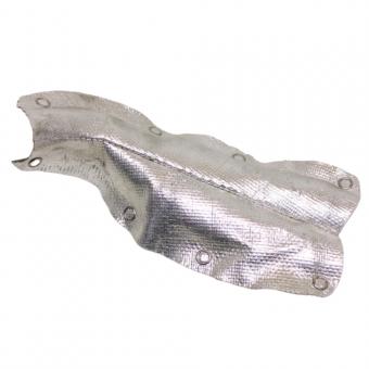
A straight tubular sleeve may not fit around a large molded connector. For these cases, BSTFLEX can develop a Custom-Shaped Aluminized Fiberglass Automotive Heat Shield around the actual component geometry.
Wire harnesses frequently divide into several branches near the engine. A conventional straight sleeve may protect the main trunk but leave the breakout point exposed.
Possible solutions include:
The selected construction should not create sharp edges, excessive bulk or pressure on the individual cable branches.
An aluminized sleeve should be installed with the reflective surface exposed toward the exhaust manifold, turbocharger or other external radiant heat source.
Avoid installation conditions that:
Where sleeve orientation is critical, the design may require clips, eyelets, ties, sewn locating features or another mechanical retention method.
A reflective sleeve is intended primarily to reduce radiant heat reaching the protected component. The space between the heat source and reflective surface is part of that thermal arrangement.
Compressing the sleeve directly against an exhaust component introduces conductive heat and can change the performance of the system.
During vehicle design and assembly, check whether engine movement, vibration or harness sag can reduce the intended air gap under operating conditions.
A sleeve that is too tight may be difficult to install, restrict harness flexibility or distort the reflective layer.
A sleeve that is too loose may move away from the protected zone, interfere with nearby components or create inconsistent positioning.
Provide the following dimensions when specifying a sleeve:
For a slide-on sleeve, connector size may be more important than the main harness diameter. If the connector cannot pass through the selected sleeve, a wrap-around or self-closing design should be considered.
A correctly selected thermal sleeve cannot protect the harness if it moves away from the heat-exposed section.
Potential retention methods include:
The retention method should prevent axial movement and rotation without compressing or damaging the wiring.
The relative position of the engine, turbocharger, exhaust system and vehicle body can change during acceleration, deceleration and normal vibration.
A harness that appears to have acceptable clearance during static inspection may approach a hot or abrasive component while the powertrain moves.
Review:
Thermal protection and mechanical protection should be evaluated together.
Engine-bay wiring sleeves may be exposed to oil mist, water, road contamination, coolant or other automotive fluids. The harness may also rub against brackets or adjacent components.
The complete sleeve construction should therefore be assessed for:
Fiberglass, aluminum, adhesive, sewing thread and closure materials may each respond differently to the operating environment.
The protected section ends inside the radiant heat zone, leaving the adjacent cable or connector exposed.
The cable is covered, but the connector remains close to the manifold or turbocharger.
A reflective sleeve is used as though it were continuous-contact exhaust insulation.
Vehicle vibration causes the sleeve to shift away from the intended position.
Large connectors or branch points prevent slide-on installation.
The harness remains too close to the heat source when a routing or retention change should have been made first.
Different reflective layers, fiberglass structures, adhesives, seams and wall thicknesses can produce different installation and thermal characteristics.
| Heat-Source Location | Primary Risk | Recommended Starting Approach |
|---|---|---|
| Beside an exhaust manifold | Broad radiant heat exposure | Improve clearance and use an aluminized reflective sleeve |
| Near a turbocharger turbine housing | Concentrated radiant heat and restricted space | Reflective or multi-layer sleeve with secure retention |
| Near a downpipe | Radiant heat and possible harness movement | Reflective sleeve, routing control and abrasion protection |
| At a sensor lead | Short cable section close to exhaust gas path | Small-diameter sleeve with controlled termination |
| Around a large connector | Irregular geometry and lower component temperature limit | Custom-shaped or wrap-around shield |
| Existing assembled harness | Connectors prevent tubular installation | Hook-and-loop, snap or self-closing sleeve |
| Very limited clearance | Radiant and possible conductive heat | Review routing and combine source-side and harness protection |
Prototype testing should reproduce the actual installation as closely as practical.
Important validation variables include:
Where an OEM specification references a particular test method, the exact proposed sleeve construction should be evaluated under the required conditions.
A material temperature rating or test result from a different sleeve construction should not automatically be applied to the new assembly.
A prototype sleeve must also be practical to manufacture and install consistently in production.
OEM design control may include:
Dedicated cutting fixtures, sewing templates or inspection gauges may be appropriate when dimensional features must remain consistent through volume production.
For an efficient technical review, provide the following information:
| Required Information | Purpose |
|---|---|
| Harness outside diameter | Defines the required sleeve size |
| Connector and branch dimensions | Determines whether tubular installation is possible |
| Protected length | Defines the thermal coverage zone |
| Heat-source type | Identifies whether the source is a manifold, turbocharger, downpipe or another component |
| Heat-source temperature | Indicates thermal severity |
| Minimum clearance | Supports radiant heat assessment |
| Maximum allowed harness temperature | Defines the required thermal reduction |
| Installation sequence | Determines slide-on or wrap-around construction |
| Harness movement | Supports retention and abrasion design |
| Fluid and environmental exposure | Supports complete material selection |
| Required validation | Defines testing and documentation requirements |
| Annual quantity | Supports production and tooling planning |
BSTFLEX manufactures reflective and textile thermal protection components for automotive wire harnesses, sensor cables, hoses and fluid lines.
Available constructions include:
Diameter, length, material structure, insulation layers, closure method, cutouts, notches, retention features and packaging can be developed according to drawings, samples and installation requirements.
For a broader overview of materials and sleeve designs, see Automotive Wire Harness Heat Protection Sleeves: Materials, Designs and Applications.
If the protected harness continues into the transmission area, see Transmission Wire Harness Heat Protection Sleeve: Design and Thermal Requirements.
For a custom project, send BSTFLEX the harness drawing, connector dimensions, protected length, heat-source temperature, minimum clearance, required harness temperature, installation photographs and expected annual quantity.
Begin by increasing distance from the manifold and securing the harness route. Where radiant heat remains significant, use a correctly sized aluminized reflective sleeve and maintain an appropriate air gap. The final assembly should be validated against the required cable and connector temperature limits.
An aluminized reflective sleeve is primarily intended to reduce radiant heat. Continuous direct contact introduces conductive heat and may require improved routing, additional insulation or a different shielding system.
An aluminized fiberglass sleeve is often a suitable starting point for radiant heat. Very close or prolonged exposure may require a multi-layer construction or combined turbocharger and harness shielding.
There is no universal clearance that applies to every vehicle. Required distance depends on turbocharger temperature, operating cycle, airflow, sleeve construction and the maximum temperature permitted for the harness and connector.
Yes. Hook-and-loop, snap-closure, self-closing and other wrap-around constructions can be installed around many completed harnesses without passing the connectors through a tubular sleeve.
The reflective surface should normally face the external radiant heat source. The underlying textile structure remains toward the protected harness.
The sleeve should cover the complete heat-exposed section and normally extend beyond the most intense radiant zone. Connector position, branches, clips and nearby heated surfaces should be considered when defining the final cut length.
The same material family may be used, but diameter, wall construction, flexibility, closure and termination can differ substantially. Each harness section should be sized and specified according to its geometry and thermal environment.
Yes. Component-specific textile heat shields can be developed around connectors, branches, sensors, valves and other irregular geometries using customer drawings, measurements or physical samples.
Provide the harness diameter, protected length, connector geometry, heat-source temperature, minimum clearance, maximum permitted harness temperature, installation method, mechanical requirements, validation standard and estimated annual volume.

No.10, Chuangxin North Road, Nanshan Park, Ningguo Economic and Technological Development Zone, Ningguo City, Anhui Province, China
tel/Whatsapp : 0086-15856303740
e-mail : sales@bstbraidedsleeve.com
Skype : vanesa-cheng